
A replacement gate valve can match the pipe size and still fail to fit the installation. The drawing helps you check the details a product photograph cannot show: face-to-face length, flange drilling, opening height and access to the handwheel or actuator. This guide explains how to read those details, identify the main components and compare a drawing with the requirements of your line.
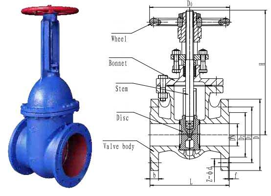
1. Start with the Drawing Type and Revision
An outline drawing is useful for layout and installation. A sectional assembly drawing shows how the parts fit together. A component drawing adds machining dimensions and tolerances. Check which document you have before using it to approve a purchase or plan a replacement.

1.1 The Main Parts of a Gate Valve Drawing
A drawing or drawing set usually brings together the following information. Some installation drawings include only the dimensions needed by the purchaser; detailed manufacturing information may be on separate sheets.
- Title block: Find the model, tekening nummer, revision, units and issue date. Make sure the revision matches the valve being quoted. A drawing for a similar-looking model may use a different flange pattern or face-to-face length.
- Views and sections: The elevation shows the overall shape; a sectional view exposes the gate, stang, seats and bonnet. A plan or end view helps you check flange drilling, handwheel position and the space needed around the valve.
- Dimensions: Separate installation dimensions from manufacturing dimensions. For fit-up, start with face-to-face length, overall height, flange details and the operating envelope. DN or NPS alone is not enough to confirm interchangeability.
- Material references: Follow each item number to the parts list. Read body, hek, stang, seat and packing materials separately. Bijvoorbeeld, WCB and CF8 identify different body materials; a stainless body does not mean every internal part uses the same grade.
- Technical notes: Look for the specified design and connection standards, pressure-temperature rating, test requirements and any special operating conditions. Notes and referenced documents are part of the drawing, not optional background.
- Parts list: Item numbers connect the section view to the names, quantities and materials of the components. Use these references when discussing trim, seals or spare parts so that both parties mean the same component.
1.2 Symbols, Dimensions and Referenced Standards
Read the legend and notes before interpreting a symbol. A piping symbol identifies a function in a system; a manufacturing drawing uses dimensions, sections and callouts to define the actual valve.
- Connections: Identify flanged, threaded or welded ends from their details and callouts. For flanges, check the standard, maat, pressure designation and facing. Do not infer connection type from a circle or triangle without the drawing legend.
- Seats and seals: Read the material description and detail view. Metal seating, resilient seating and packing are different parts of the sealing system; a product code or simplified sketch does not describe all of them.
- Tolerances and fits: A diameter with a tolerance or fit designation controls a particular interface. Read it with the units and general tolerances. It should not be copied to another size or component.
- Surface finish: A roughness callout applies to the surface indicated. Seat geometry, materiaal, finish and assembly all affect sealing; a lower roughness number alone is not a valve leakage guarantee.
Different standards cover different details. A design standard, a flange standard and a face-to-face standard do not replace one another. Ons industrial valve standards guide explains how these references fit together; use the standard and edition specified for the project.
2. Read the Valve from Body to Operator
Working through the section view in a consistent order makes discrepancies easier to spot. Start with the pressure-containing body, then follow the gate, zitplaatsen, stem and operator.
2.1 Lichaam, Bore and End Connections
The body drawing defines the pressure boundary and the pipe connections. For a purchaser, the important checks are material, rating and fit. Detailed wall dimensions are assessed against the applicable design requirements.
Pay particular attention to these three areas:
- Wall thickness and material: Use the material specification and design standard stated on the drawing. There is no single wall-thickness value that can be applied to every valve of a given DN and PN without knowing its design basis.
- Bore: DN or NPS is a nominal designation. Where actual clear bore matters, use the dimension on the drawing or request it. Do not assume the nominal size is the measured internal diameter.
- Flange details: Check outside diameter, bolt-circle diameter, hole count, hole size and facing against the mating flange. A valve can share the same nominal size and pressure label but still have incompatible connection details.
For a replacement, compare the end-to-end or face-to-face dimension before ordering. Existing pipework usually leaves less freedom than a new installation, and forcing a mismatch into place can load the valve and joints.
2.2 Gate and Seating Arrangement
A sectional drawing shows whether the valve uses a wedge, parallel discs or another construction. This is more reliable than identifying the design from its external appearance.
Check the following details together:
- Gate form: Identify solid, flexible or split wedge construction, or the relevant parallel arrangement. See the wedge and parallel gate valve comparison for the main differences. Neither the gate angle nor the number of discs alone determines the pressure rating.
- Seating detail: Look for integral or replaceable seats, metal or resilient sealing, and any overlay material. If a detail shows a thickness or angle, it belongs to that component and drawing revision.
- Material combination: Read gate and seat materials alongside the body material and service conditions. A corrosion-resistant body cannot compensate for an unsuitable stem, seat or seal.
The seat detail may show how a ring is retained and how the gate contacts it. Keep these construction notes separate from the acceptance test: a drawing of the seat does not by itself define the permitted leakage.
2.3 Stang, Handwheel and Actuator
Follow the stem from the gate to the operator. The drawing should make the movement and required clearance clear enough to plan access around the installed valve.
- Stem dimensions: Read the diameter, thread and material references from the actual drawing. For replacement parts, include the model and drawing revision; the nominal valve size does not establish the stem dimensions.
- Movement and fit: On a rising-stem valve, allow for the stem at full opening. On a non-rising-stem design, still check access to the handwheel and bonnet. De Besturingssysteem&Y and NRS comparison explains this layout difference.
- Operator envelope: Check handwheel diameter, gearbox orientation and removal space. For an actuator, confirm the mounting interface, required thrust or torque, supply and control requirements for the selected valve.
2.4 Kap, Gasket and Packing
The bonnet closes the body, the bonnet gasket seals that joint, and the stem packing seals around the moving stem. These functions should be identifiable in the parts list and section view.
Check bonnet attachment, pakking materiaal, packing arrangement and access to the gland. Bolt sizes and packing dimensions are model-specific. When planning maintenance, also allow room to lift the bonnet or withdraw the stem and gate where the construction requires it.
3. Technical Notes and Inspection Requirements
The drawing should agree with the specification, quotation and approved inspection requirements. When a note refers to another document, check that document and its revision rather than filling the gap with a typical value.
3.1 Material Requirements
Read the parts list and material notes with the application in mind:
- Check the specified casting or forging grade for the body and bonnet, and the separate grades for the internal components.
- For stainless steel, distinguish the grade and product form. A general stainless description does not establish compatibility with every chemical.
- For drinking-water duty, identify the material, coating and approvals required for the project and destination market.
Where traceability or inspection documents are required, agree them with the enquiry or order. A material name, generic test example or company photograph does not replace a certificate tied to the supplied product.
3.2 Assembly and Operating Notes
Useful assembly notes explain how the valve should move and what must be checked before service:
- Confirm end connections and thread or flange specifications where applicable; these must match the intended pipe connection.
- Check the gate position at full opening and closing, and any travel stops or position indicators shown.
- Confirm the operating direction, access for adjustment and the functional checks required by the model instructions.
3.3 Reading the Test Requirements
A test requirement needs a method, medium, druk, duration and acceptance criterion. The table below shows what to look for in the agreed documents; it is a reading aid, not a universal test schedule.
| Test or check | Medium | Pressure or load | Duur | Acceptance reference |
|---|---|---|---|---|
| Shell integrity | As specified | Applicable test standard and valve rating | Standaard, size and test procedure | Specified pressure-boundary acceptance criteria |
| Seat tightness | As specified | Specified closure-test pressure | Applicable test procedure | Specified leakage class or acceptance criteria |
| Gas seat test, if required | Specified gas | Agreed gas test procedure | Applicable test procedure | Specified leakage criterion |
| Operating or torque check, if required | As applicable | Model-specific operating load | Agreed procedure | Required travel and operating performance |
Routine production tests and type tests serve different purposes. If the project requires a particular inspection scope, witnessed test or report, agree it before ordering. The required pressure, duration and leakage criterion should be confirmed for the actual valve.
4. What Changes with the Application
The same nominal size can be supplied with different materials, connections and operators. Use the application to decide which drawing details need the closest attention.
4.1 Water Supply and Drainage
For a water line, check the installation environment as well as the medium:
- Read the body, gate and coating specifications; buried, exposed and submerged installations may have different needs.
- Check the bore and seating arrangement where sediment or solids may be present.
- Compare open and closed heights with the chamber, cover or overhead obstruction; do not assume every non-rising-stem valve shares one height.
- Confirm any project-specific drinking-water or coating requirements separately.
Farpro lists Z41X/Z45X resilient gate valves among its water-system options. Use the selected model drawing to compare connection dimensions and operating clearance with the installation.
4.2 Chemical Service
Chemical compatibility depends on the medium, concentration and operating conditions. Read the complete wetted-material specification rather than choosing from the body name alone.
- Check the body and trim grades against the actual chemical and concentration.
- Check seat, packing and gasket materials as well as the metal parts.
- Read the pressure-temperature rating for the complete construction, including any soft sealing elements.
- Confirm any special cavity, venting or isolation arrangement from the approved design; it should not be inferred from a generic drawing.
4.3 High-Temperature and High-Pressure Service
In demanding service, material grade, rating and operating loads need to be considered together. A larger wall dimension or a familiar standard name alone is not sufficient evidence of suitability.
- Read the specified body, motorkap, stem and trim materials and any heat-treatment requirements.
- Check the relevant design basis, rating and connection details for the operating temperature.
- Identify seat construction and any overlay or hard-facing specification shown.
- Check the inspection procedure and any additional tests agreed for the project.
If fire testing is a project requirement, confirm the relevant standard and qualification for the offered design. A reference to a general gate-valve design standard does not by itself establish fire-test certification.
5. Common Reading Mistakes and a Practical Check
Most fit-up problems start with an assumption: that two valves with the same DN are interchangeable, or that a photograph shows all the clearance needed. A short document check is often more useful than reading every manufacturing detail.
5.1 Common Misunderstandings
- Stem movement: Confusing the closed height with the maximum height of a rising-stem valve. Use the full-open envelope when checking overhead clearance.
- Pressure and temperature: Treating a nominal pressure designation as the allowable pressure at every temperature. Use the relevant pressure-temperature rating.
- Standard references: Assuming a design-standard reference also fixes flange drilling and face-to-face length. Check each applicable reference and the dimensions actually shown.
- Material names: Treating CF8 and CF8M as interchangeable for every service. Confirm the complete wetted-material combination against the medium.
5.2 A Practical Review Before Ordering
- Identify the document: Match the model, maat, rating and revision to the quotation. Resolve discrepancies before approving the drawing.
- Check the fit: Compare face-to-face length, end connections and operating clearance with the existing line or equipment layout.
- Check the duty: Match the medium, druk, temperature and inspection requirements to the proposed materials and construction.
- Ask about the detail that is unclear: A marked-up drawing or a photograph of the existing installation helps us understand the issue more quickly than a nominal size alone.
6. Choosing the Right Drawing for Your Enquiry
For a replacement, an outline drawing and connection details are usually the starting point. For spare parts or internal construction, the assembly drawing and parts list become more important. Ask for the document that answers the decision you need to make.
If you are comparing Farpro schuifafsluiters, send the size, rating and connection standard, together with any space constraint. We can discuss the appropriate model and the drawing information needed for your enquiry.
For an existing installation, a sketch of the available space or a photo of the nameplate can make the first conversation easier. Contact our team with what you have, and we can work through the remaining details.