
Industrial valve replacement starts with a clear specification and a planned shutdown. A replacement must fit the pipeline, perform the required function and suit the operating conditions. This guide covers the information buyers and maintenance teams should prepare before ordering and the main stages of a controlled replacement.
1. Record the Existing Valve and Service Conditions
Identify the valve type, model, body and trim materials, nominale maat, pressure designation and end connections. Record the fluid, normal and design pressure, operating and design temperature, and whether the valve isolates flow, regulates flow or prevents backflow.
Also check face-to-face dimensions, flange drilling and facing, flow direction where applicable, installation orientation, stem clearance and actuator connections. A valve with the same nominal size may still have different dimensions or operating requirements.
2. Select the Replacement Against the Complete Specification
Compare the proposed valve with the piping specification and the required duty. Use the pressure-temperature rating of the selected configuration, not nominal pressure alone. Check the body, zitplaatsen, packing and gaskets for fluid compatibility.
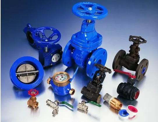
- Schuifafsluiters are generally used for fully open or fully closed isolation.
- Bolkleppen can be considered where regulating duty is required.
- Terugslagkleppen prevent reverse flow; their selection depends on the system conditions.
- Vlinderkleppen offer compact quarter-turn operation in suitable configurations.
For an actuated valve, include the available power or air supply, control signal, operating duty and any required fail position.
3. Prepare the Shutdown and Installation Plan
Before work begins, confirm the approved work procedure, responsible personnel, required parts, lifting and pipe-support arrangements, inspection criteria and restart plan. Have the replacement valve, suitable gaskets, fasteners and manufacturer’s installation instructions available.
Qualified personnel must control all relevant energy sources, inclusief het proces, actuator and any stored pressure. Isolate the equipment, apply the site’s lockout procedure, release or control residual pressure, drain or manage the medium, and verify the safe condition before opening any connection. A stopped pump or closed control valve alone does not establish that the section is safe to dismantle.
4. Remove the Old Valve and Inspect the Connections
After the safe condition has been verified, support the valve and pipework before disconnecting the assembly. Use the approved removal method and suitable lifting equipment. Check flange faces, mating dimensions and alignment for damage or distortion.
Identify why the original valve needs replacement. Lekkage, corrosie, seat wear, operating problems or unsuitable materials may require a change in specification, rather than another valve of the same model.
5. Install the Replacement
Check the delivered valve identification against the order. Confirm orientation and flow direction where specified. Position suitable gaskets and align the connections before tightening. Do not use the valve or flange bolts to force misaligned pipework into position.
Follow the valve, gasket and fastener manufacturers’ requirements for the tightening method and torque. Connect the actuator and controls as specified, with adequate access for operation and maintenance. Welded installations require their own approved welding and inspection procedures.
6. Inspect, Test and Return to Service
Carry out the agreed installation checks and tests using the approved procedure. Confirm valve operation, external sealing and any required control functions. Test conditions must suit the valve and the connected system; there is no single pressure or sequence appropriate for every installation.
When the installation is accepted, authorized personnel should return the system to service in a controlled manner. Monitor for leakage, unusual operation or pressure transients, and record the valve identification, test results and maintenance information.
What to Include in a Replacement Valve Inquiry
- Existing valve photographs, nameplate or model information.
- Required valve function, fluid, maat, pressure and temperature.
- Connection standard, face-to-face length and available clearance.
- Materialen, operatie, inspection requirements and quantity.
- Delivery destination and required project date.
This overview supports procurement and planning. The site’s approved work procedure and the specific manufacturer’s instructions govern the actual replacement.
Discuss Your Valve Requirements with Farpro
For a valve quotation or replacement inquiry, send the fluid, valve size, druk, temperatuur, connection standard, quantity and destination. Email your valve schedule or drawings to service@farprovalve.com, of contact Farpro Valve to discuss the application.
Further Reading
OSHA: controlling hazardous energy during maintenance.
Replacing an Unidentified or Obsolete Valve
An old nameplate is not always readable, and a model number may no longer lead to a current catalogue. In that situation, photographs of the body markings, end connections and operator can help identify the construction. A dimensioned sketch of the installation is often more useful than an uncertain model reference.
For a flanged replacement, compare the face-to-face length, flange outside diameter, bolt pattern and facing as well as the nominal size. PN and Class markings describe different rating systems; similarly named sizes do not establish that two flanges will mate. Do not alter an installed flange simply to accommodate a replacement without an approved engineering decision.
Farpro's schuifafsluiters, kogelkranen En terugslagkleppen provide starting points for identifying a replacement. If the original model is uncertain, send us the photographs and installation dimensions so the proposed valve can be compared with the existing pipework.