Dalam sistem perpipaan industri, katup gerbang berfungsi sebagai peralatan utama untuk mengendalikan on-off cairan. Setiap tautan desain mereka, produksi, instalasi, dan pemeliharaan bergantung pada akurat gambar katup gerbang untuk bimbingan. Gambar katup gerbang bukan hanya itu “bahasa komunikasi” untuk tenaga teknik dan teknis tetapi juga dasar inti untuk memastikan kinerja katup dan keamanan sistem. Apakah Anda seorang pemula yang baru mengenal industri katup atau ahli teknis berpengalaman, kemampuan Anda untuk menafsirkan gambar katup gerbang secara akurat secara langsung memengaruhi efisiensi kerja dan kualitas proyek. Artikel ini akan dimulai dengan komposisi dasar gambar gate valve, dan secara bertahap mempelajari konten utama seperti interpretasi komponen inti, penerapan standar teknis, dan seleksi berdasarkan skenario. Dikombinasikan dengan kasus praktis dari perusahaan terkenal seperti farpro valve, ini akan memberi Anda panduan komprehensif dan profesional untuk menafsirkan gambar katup gerbang.
SAYA. Pemahaman Dasar Gambar Gate Valve: Pegang “Kerangka” Gambar
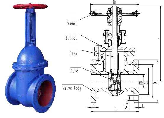
Gambar katup gerbang adalah dokumen teknik yang mengintegrasikan spesifikasi gambar mekanis dan standar industri katup. Fungsi intinya adalah untuk menyampaikan dimensi struktural dengan jelas, pemilihan materi, persyaratan teknis, dan spesifikasi pemasangan katup gerbang. Sebelum mendekati gambar tertentu, perlu menguasai komposisi dasar dan aturan umumnya, yang mana “batu loncatan” untuk menafsirkan gambar.

1.1 Komponen Inti Gambar Katup Gerbang
Menurut standar gambar industri dan spesifikasi industri katup, satu set lengkap gambar katup gerbang biasanya mencakup yang berikut ini 6 bagian inti, yang saling berkaitan dan bersama-sama membentuk suatu sistem informasi teknis yang utuh:
- Blok Judul: Terletak di sudut kanan bawah gambar, itu berfungsi sebagai “kartu identitas” dari gambar tersebut. Itu termasuk nama gambarnya (MISALNYA., “Katup Gerbang Bergelang Baja Tahan Karat Z41W-16P”), nomor gambar (MISALNYA., “FP-ZG-2025-001”, Di mana “FP” bisa singkatan dari farpro valve), skala (umumnya 1:5, 1:10, dll.), satuan desain, tanggal desain, pengulas, dan informasi lainnya. Blok judul gambar katup gerbang farpro valve juga menandai standar penerapan produk, seperti API 600 atau GB/T 12234 (Standar Nasional Republik Rakyat Tiongkok untuk Katup Gerbang Baja), memfasilitasi pengguna untuk menelusuri dasar kualitas.
- Lihat Sistem: Katup gerbang memiliki struktur yang kompleks dan perlu ditampilkan melalui kombinasi beberapa tampilan. Tampilan utama biasanya mengadopsi tampilan sectional (MISALNYA., bagian penuh, setengah bagian) untuk menunjukkan dengan jelas struktur internal seperti badan katup, gerbang, dan batang katup; tampilan samping digunakan untuk menampilkan dimensi pemasangan dan kontur luar katup; tampilan atas berfokus pada refleksi dimensi sambungan flensa atau posisi roda tangan. Untuk katup gerbang dengan struktur khusus (seperti katup gerbang batang tidak naik), tampilan lokal yang diperbesar juga ditambahkan untuk menandai detail seperti permukaan penyegelan dan benang.
- Penandaan Dimensi: Ini dibagi menjadi dua kategori: dimensi struktural dan dimensi pemasangan. Dimensi struktural mencakup parameter utama seperti ketebalan dinding badan katup, ketebalan gerbang, dan diameter batang katup, yang secara langsung mempengaruhi kekuatan katup; dimensi pemasangan mencakup diameter flensa, jumlah dan jarak lubang baut, tinggi katup total, jarak ujung koneksi, dll., dan merupakan dasar inti untuk instalasi pipa. Misalnya, untuk katup gerbang DN100 PN40, gambar akan dengan jelas menandai bahwa ketebalan dinding minimum badan katup adalah ≥6.4mm, dan diameter batang katup ≥17.5mm (sesuai dengan Q/TC 001-2022 standar).
- Penandaan Bahan: Nilai materi ditandai dengan kata atau kode di samping setiap komponen. Misalnya, badan katup ditandai dengan “CF8” (304 besi tahan karat), batang katup dengan “316”, dan segel dengan “PTFE + Grafit”. Dalam gambar katup gerbang baja tahan karat farpro valve, secara khusus dicatat bahwa materi tersebut mematuhi GB/T 12225 (Standar Nasional Republik Rakyat Tiongkok untuk Katup Paduan Tembaga) atau standar ASTM, memastikan bahwa ketahanan korosi sesuai dengan lingkungan industri.
- Persyaratan Teknis: Bagian ini menjelaskan indikator kinerja secara terpusat, akurasi pemrosesan, persyaratan pengujian katup gerbang dalam bentuk teks, seperti “Tekanan uji cangkang adalah 1.5 kali tekanan nominal, tidak ada kebocoran untuk 60 detik berturut-turut”, “Kekasaran permukaan penyegelan Ra ≤ 3,2μm”, “Roda tangan menutup searah jarum jam dan membuka berlawanan arah jarum jam”.
- Daftar Bagian: Ini mencantumkan nomor seri, nama, kuantitas, dan material dari seluruh bagian komponen gate valve, seperti badan katup, gerbang, penutup katup, batang katup, roda tangan, sedang mengemas, dll.. Ini adalah referensi penting untuk pengadaan produksi dan perakitan. Dalam gambar katup gerbang Z41W dari Shanghai Langu Valve, daftar bagian dapat mencakup 18 item informasi bagian, meliputi seluruh komponen mulai dari bodi utama hingga aksesoris.
1.2 Simbol Umum dan Spesifikasi Gambar Gate Valve
Gambar katup gerbang mengadopsi simbol gambar mekanis umum dan mengintegrasikan pengidentifikasi khusus industri katup. Menguasai simbol-simbol ini adalah dasar untuk menafsirkan gambar dengan cepat:
- Simbol Metode Koneksi: Koneksi flensa diwakili oleh “○”, koneksi berulir oleh “∟”, dan sambungan las oleh “△”. Simbol-simbol ini ditandai dengan jelas pada kedua ujung katup pada gambar. Misalnya, pada gambar katup gerbang bergelang katup farpro, flensa ditandai dengan kode standar “JB/T 79.1” (Standar Industri Mekanik Republik Rakyat Tiongkok untuk Flensa Muka yang Ditinggikan), menunjukkan bahwa dimensi flensa memenuhi spesifikasi ini.
- Simbol Permukaan Penyegelan: Segel lunak diwakili oleh “⊂⊃”, dan segel keras “□□”. Pada saat yang sama, kode bahan segel ditandai (MISALNYA., “F” mewakili fluororubber). Untuk katup gerbang dengan segel logam-ke-logam, gambar akan menunjukkan bahan permukaan dari permukaan penyegelan, seperti “STL” (paduan keras).
- Simbol Toleransi dan Kesesuaian: Bagian-bagian penting seperti kesesuaian antara batang katup dan mur batang katup, dan kesesuaian antara gerbang dan dudukan katup akan ditandai dengan tingkat toleransi, seperti “φ20H7/f6”, Di mana “H7” adalah toleransi lubang dan “f6” adalah toleransi poros, memastikan fleksibilitas dan penyegelan bagian yang bergerak.
- Simbol Kekasaran Permukaan: Diwakili oleh “√” dan nilai numerik. Misalnya, permukaan badan katup ditandai dengan “√Ra6.3”, dan permukaan penyegelan dengan “√Ra3.2”. Semakin kecil nilainya, semakin halus permukaannya dan semakin baik kinerja penyegelannya.
Selain itu, gambar katup gerbang harus memenuhi standar terpadu. Di dalam negeri, GB/T 12221 (Panjang Struktural Katup) dan GB/T 1047 (Ukuran Nominal untuk Pipa dan Perlengkapannya) umum digunakan. Secara internasional, API 600 (Standar American Petroleum Institute untuk Katup Gerbang Baja) dan BS 1414 (Standar Inggris untuk Katup) diadopsi. Sebagai perusahaan katup global, katup farpro menandai standar nasional dan internasional pada gambarnya untuk memenuhi kebutuhan pelanggan di berbagai wilayah.
II. Interpretasi Gambar Komponen Inti Katup Gerbang: Analisis Korelatif dari Struktur ke Kinerja
Inti kinerja katup gerbang bergantung pada desain komponen utama seperti badan katup, gerbang, dan batang katup. Penandaan parameter komponen-komponen ini dalam gambar secara langsung menentukan ketahanan tekanan, kinerja penyegelan, dan masa pakai katup. Berikut ini akan dijelaskan poin-poin penting dari gambar masing-masing komponen inti secara detail, menggabungkan detail gambar tertentu dan karakteristik produk katup farpro.
2.1 Badan Katup: Itu “Kerangka Penahan Beban” dari Gerbang Katup
Badan katup merupakan komponen utama dari katup gerbang, menahan tekanan sedang dan berperan dalam pemasangan dan fiksasi. Inti dari penandaan gambarnya adalah parameter kekuatan dan sambungan.
Dalam tampilan utama gambar, badan katup biasanya disajikan dalam tampilan bagian, dan berikut ini 3 poin-poin perlu difokuskan:
- Ketebalan dan Bahan Dinding: Gambar tersebut akan menandai ketebalan dinding setiap bagian badan katup, terutama area konsentrasi tegangan seperti akar flensa dan dasar rongga katup. Menurut Q/TC 001-2022 standar, ketebalan dinding minimum badan katup gerbang DN100 PN40 adalah ≥6.4mm. Dalam gambar katup gerbang baja tahan karat farpro valve, tunjangan proses tambahan 0,5-1 mm ditambahkan atas dasar ini untuk meningkatkan faktor keamanan. Dalam hal penandaan material, “WCB” (baja karbon) ditandai untuk kondisi kerja umum, Dan “CF8” (304 besi tahan karat) atau “CF8M” (316 besi tahan karat) untuk kondisi kerja yang korosif. Badan katup baja tahan karatnya semuanya mematuhi GB/T 12225 standar untuk memastikan ketahanan terhadap korosi.
- Dimensi Saluran Aliran: Gambar tersebut akan menandai diameter minimum saluran aliran di badan katup. Misalnya, diameter minimum saluran aliran katup gerbang DN100 adalah ≥75mm. Saluran aliran harus dirancang sebagai tipe lurus untuk mengurangi hambatan fluida. Dalam gambar katup gerbang farpro valve, dinding bagian dalam saluran aliran ditandai dengan persyaratan kekasaran “Ra ≤ 6,4μm” untuk mengurangi erosi dan keausan yang disebabkan oleh medium.
- Struktur Koneksi: Untuk badan katup dengan sambungan flensa, gambar akan menandai parameter seperti diameter flensa (D), diameter lingkaran tengah lubang baut (D1), jumlah dan diameter lubang baut (n-φd). Misalnya, flensa DN100 PN16 ditandai dengan “D=220mm, D1=180mm, n=8-φ18mm”. Tingkat kecocokan dengan flensa pipa secara langsung mempengaruhi kinerja penyegelan pemasangan.
Persyaratan teknis gambar badan katup juga akan dengan jelas menentukan standar pengujian tekanan air, seperti “Tekanan uji cangkang adalah 2,4MPa (1.5×PN16), tidak ada kebocoran untuk 60 detik”. farpro valve memeriksa semua badan katup sesuai standar ini sebelum meninggalkan pabrik untuk memastikan tidak ada lubang pasir, retak, atau cacat lainnya.
2.2 Sistem Gerbang dan Penyegelan: Itu “Inti Penyegelan” dari Gerbang Katup
Sistem penyegelan yang terdiri dari gerbang dan dudukan katup adalah kunci katup gerbang untuk mengontrol fluida. Desain gambarnya secara langsung menentukan kinerja penyegelan katup dan merupakan prioritas utama interpretasi.
Poin-poin penting penandaan gerbang pada gambar:
- Bentuk Struktural: Gambar tersebut dengan jelas akan menunjukkan jenis gerbang. Misalnya, katup gerbang baji ditandai dengan “sudut baji 5°”, yang cocok untuk penyegelan bertekanan tinggi; katup gerbang paralel ditandai dengan “gerbang ganda + musim semi”, yang cocok untuk skenario tekanan rendah dan diameter besar. Dalam gambar katup gerbang baji Z40W farpro valve, dimensi struktur pemandu gerbang ditandai secara khusus untuk mengurangi keausan selama pembukaan dan penutupan.
- Parameter Permukaan Penyegelan: Lebar, sudut, dan kekasaran permukaan penyegelan adalah tanda inti, seperti “lebar permukaan penyegelan 5mm, sudut 30°, Ra ≤ 3,2μm”. Untuk katup gerbang yang tertutup rapat, gambarnya juga akan menandai bahan permukaannya, seperti “menyegel permukaan permukaan dengan STL, ketebalan 2mm”, untuk meningkatkan ketahanan aus.
- Pencocokan Materi: Bahan gerbang harus kompatibel dengan badan katup dan medianya. Gambar itu akan menandai “bahan gerbang konsisten dengan badan katup (CF8)” atau “bahan gerbang adalah 316L, bahan badan katup adalah CF8” untuk skenario medium korosif yang kuat.
Penandaan gambar dudukan katup biasanya sesuai dengan gerbang, termasuk metode sambungan antara dudukan katup dan badan katup (seperti koneksi berulir, pengelasan), bahan penyegel (seperti “permukaan penyegelan dudukan katup ditutupi dengan PTFE”), dan persyaratan perakitan (seperti “gangguan yang pas antara dudukan katup dan badan katup, toleransi pas H7/s6”). Pada gambar sistem penyegelan katup farpro, itu ditandai dengan itu “tekanan uji segel adalah 1,76MPa (1.1×PN16), tingkat kebocoran ≤ 8mm³/s (DN100)”, yang sesuai dengan GB/T 13927 standar (Uji Tekanan Katup).
2.3 Batang Katup dan Sistem Penggerak: Itu “Pusat Operasi” dari Gerbang Katup
Batang katup menghubungkan gerbang dan perangkat penggerak dan merupakan komponen inti untuk mentransmisikan gaya operasi. Fokus penandaan gambarnya adalah pada kekuatan dan fleksibilitas.
- Dimensi dan Bahan: Gambar akan menandai diameternya, panjang, dan parameter ulir batang katup, seperti “diameter batang katup φ20mm, panjang 300mm, benang M20×2”. Dari segi materi, “20cr13” ditandai untuk kondisi kerja umum, Dan “316” untuk kondisi kerja yang korosif. Pada gambar batang katup farpro valve, secara khusus dicatat bahwa “permukaan batang katup berlapis krom, dengan ketebalan lapisan ≥ 0,05mm” untuk meningkatkan ketahanan aus dan ketahanan korosi.
- Kesesuaian dan Akurasi: Kesesuaian antara batang katup dan kotak isian penutup katup ditandai dengan “φ20H7/f6” untuk memastikan kinerja penyegelan; benang yang pas antara batang katup dan mur batang katup ditandai dengan “M20×2-6g” untuk memastikan kelancaran pembukaan dan penutupan. Gambar itu juga menandai “kelurusan batang katup ≤ 0,1 mm/m” untuk menghindari kemacetan akibat pembengkokan.
- Pencocokan Perangkat Drive: Katup gerbang manual ditandai dengan dimensi handwheel (MISALNYA., “diameter roda tangan 200mm, bahan HT200”) dan kekuatan operasi (MISALNYA., “kekuatan operasi maksimum ≤ 360N”); katup gerbang listrik ditandai dengan dimensi sambungan aktuator, persyaratan torsi (MISALNYA., “torsi aktuator ≥ 500N·m”) dan antarmuka sinyal (MISALNYA., “4-20keluaran analog mA”).
2.4 Pengepakan dan Penutup Katup: Itu “Penghalang Anti Bocor” dari Gerbang Katup
Penutup katup dan pengepakan bekerja sama untuk mencegah media bocor dari batang katup. Fokus penandaan gambarnya adalah pada keandalan penyegelan.
Gambar penutup katup ditandai dengan “ketebalan dinding penutup katup ≥ 6.4mm (konsisten dengan badan katup), dihubungkan dengan badan katup dengan baut, spesifikasi baut M16×50, kuantitas 8”, dan permukaan penyegelan mengadopsi “penyegelan paking, bahan paking 304 + grafit”. Bagian kotak isian ditandai dengan “kedalaman kotak isian 50mm, bahan kemasan PTFE + grafit fleksibel, lapisan pengepakan nomor 4”, dan dengan jelas menyatakan hal itu “celah pas antara kelenjar dan kotak isian ≤ 0,1 mm”. Pada gambar penutup katup farpro valve, itu ditandai dengan “uji ketahanan torsi 465N·m (DN100), tidak ada kerusakan untuk 10 detik”, yang memenuhi persyaratan kinerja instalasi.
AKU AKU AKU. Persyaratan Teknis dan Standar Pemeriksaan Gambar Katup Gerbang: Itu “Garis Merah” untuk Memastikan Kualitas
Persyaratan teknis bagian dari gambar katup gerbang adalah dasar inti untuk produksi dan inspeksi katup, mencakup berbagai spesifikasi seperti bahan, pengolahan, dan pengujian, yang harus diikuti dengan ketat. Berikut ini adalah interpretasi isi utama persyaratan teknis yang dikombinasikan dengan standar umum seperti Q/TC 001-2022 dan API 600.
3.1 Persyaratan Teknis Bahan
Gambar tersebut akan dengan jelas menentukan standar material dan persyaratan kinerja setiap komponen, seperti:
- Coran paduan tembaga mematuhi GB/T 12225, dan penempaan mematuhi GB/T 20078 (Standar Nasional Republik Rakyat Tiongkok untuk Katup Baja Tempa);
- Kandungan kromium bahan baja tahan karat ≥12% (sejalan dengan definisi baja tahan karat), dan uji ketahanan korosi intergranular memenuhi syarat;
- Untuk katup gerbang yang digunakan dalam air minum, bahannya harus mematuhi GB/T 17219 standar kebersihan (Standar Higienis Peralatan Air Minum dan Bahan Pelindung) tanpa pengendapan logam berat.
Dalam gambar katup gerbang baja tahan karat farpro valve, nomor sertifikat mutu bahan juga ditandai untuk memastikan ketertelusuran bahan. Ketahanan korosi pada material baja tahan karatnya telah diverifikasi melalui uji semprotan garam, tidak menunjukkan karat 500 jam.
3.2 Persyaratan Pemrosesan dan Perakitan
Persyaratan ini secara langsung mempengaruhi keakuratan dan kinerja katup, dan tanda inti termasuk:
- Ulir badan katup mematuhi GB/T 7307 (Benang Pipa Silinder) atau GB/T 12716 (60° Segel Benang), dan deviasi sudut sumbu ulir adalah ≤1°;
- Saat gerbang terbuka penuh, itu tidak boleh tinggal di saluran badan katup; ketika ditutup, garis tengah permukaan perapat lebih tinggi dari permukaan perapat badan katup;
- Setelah perakitan, katup membuka dan menutup secara fleksibel, tanpa macet setelahnya 5 operasi berturut-turut, dan arah buka tutup handwheel ditandai dengan jelas (menutup searah jarum jam, terbuka berlawanan arah jarum jam).
3.3 Standar Pengujian dan Inspeksi
Gambar akan dengan jelas menentukan itemnya, metode, dan standar kualifikasi inspeksi pabrik dan inspeksi jenis, yang merupakan jaminan akhir kualitas katup. Penandaan umum ditunjukkan pada tabel berikut:
| Jenis Tes | Sedang | Tekanan Uji | Lamanya | Kriteria Kualifikasi |
|---|---|---|---|---|
| Tes Kerang | Cairan | ≥1,5 kali tekanan nominal | DN≤50: 15S; DN65-100: 60S | Tidak ada kerusakan struktural, tidak ada kebocoran |
| Tes Segel | Cairan | ≥1,1 kali tekanan nominal | Sama seperti di atas | Tingkat kebocoran ≤ 0,08×DN mm³/s |
| Tes Segel Gas | Gas | 0.6±0,1MPa | Sama seperti di atas | Tidak ada gelembung udara yang meluap |
| Uji Ketahanan Torsi | — | DN100: 465N·m | 10S | Tidak ada kerusakan, lulus uji cangkang/segel |
Dalam gambar katup gerbang farpro valve, “ketik kondisi pemicu pengujian” juga ditandai, termasuk finalisasi produk baru, perubahan material/proses yang besar, dan dimulainya kembali produksi setelah setengah tahun terhenti. Aturan pengambilan sampel diterapkan sesuai dengan “DN50-100: 3 unit yang diambil sampelnya 20 unit”, dan pengujian item lengkap dilakukan untuk memastikan kualitas batch yang stabil.
IV. Perbedaan Gambar Katup Gerbang Berdasarkan Skenario Berbeda: Itu “Dasar Inti” untuk Seleksi
Katup gerbang digunakan dalam berbagai skenario, dari pasokan air dan drainase kota hingga bidang industri seperti industri kimia, tenaga listrik, dan minyak bumi. Kondisi kerja yang berbeda memiliki persyaratan kinerja yang berbeda secara signifikan untuk katup gerbang, yang tercermin dalam gambar sebagai desain parameter dan struktur yang ditargetkan. Berikut ini akan ditafsirkan perbedaan poin-poin penting dari gambar-gambar tersebut dalam kombinasi dengan skenario-skenario umum.
4.1 Skenario Penyediaan Air dan Drainase: Fokus pada Ketahanan Korosi dan Kenyamanan Pemasangan
Dalam sistem pasokan air dan drainase kota, katup gerbang harus tahan terhadap korosi tanah dan gerusan oleh kotoran dalam air. Poin-poin penting dalam penandaan gambar meliputi:
- Bahan badan katup ditandai dengan “besi ulet QT450-10” atau “baja tahan karat CF8”, dan dinding bagian dalam ditandai dengan “lapisan resin epoksi, ketebalan ≥ 300μm” untuk mencegah karat;
- Saluran aliran ditandai dengan “tipe langsung, diameter ≥ DN” untuk mengurangi akumulasi sedimen dan menghindari penyumbatan;
- Dimensi pemasangan ditandai dengan “struktur batang tidak meninggi, tinggi total ≤ 600mm” untuk beradaptasi dengan ruang sempit seperti galeri pipa bawah tanah;
- Persyaratan kebersihan ditandai dengan “mematuhi GB/T 17219, sertifikasi keamanan air minum”.
Untuk gambar katup gerbang katup farpro dirancang untuk skenario pasokan air dan drainase, A “alur pengikisan lumpur” struktur dirancang khusus, yang ditandai di bagian bawah gerbang untuk secara efektif menghilangkan sedimen pada permukaan penyegelan dan meningkatkan masa pakai.
4.2 Skenario Industri Kimia: Fokus pada Ketahanan Korosi dan Keandalan Penyegelan
Media kimia sebagian besar adalah cairan korosif asam-basa, dengan fluktuasi besar dalam tekanan dan suhu. Inti dari penandaan gambar adalah ketahanan terhadap korosi material dan kinerja penyegelan:
- Bahan badan katup dan gerbang ditandai dengan “316L baja tahan karat” atau “Hastelloy C276”, dan dicatat bahwa “tahan terhadap 30% asam sulfat, suhu ≤ 180℃”;
- Permukaan penyegelan ditandai dengan “segel keras dari logam ke logam, muncul ke permukaan dengan Hastelloy” untuk menghindari korosi pada segel lunak;
- Tekanannya ditandai dengan “Pn40, suhu kerja -20℃ ~ 180℃”, dan ketebalan dinding badan katup dirancang sesuai dengan standar PN63 untuk memberikan margin keamanan;
- Rongga tengah ditandai dengan “lubang pelepas tekanan tambahan untuk mencegah peningkatan tekanan yang disebabkan oleh akumulasi sedang”.
4.3 Skenario Suhu Tinggi dan Tekanan Tinggi (MISALNYA., Tenaga Listrik, Minyak bumi): Menekankan Kekuatan dan Ketahanan Suhu Tinggi
Dalam skenario suhu tinggi dan tekanan tinggi, katup gerbang harus tahan terhadap kondisi kerja yang ekstrim. Fokus penandaan gambar adalah kekuatan dan stabilitas termal:
- Bahan badan katup ditandai dengan “baja krom-molibdenum WC9”, dan batang katup ditandai dengan “25Cr2MoV”, dan dicatat bahwa “perlakuan temper suhu tinggi, kekerasan HB220-250”;
- Dimensinya ditandai dengan “ketebalan dinding badan katup ≥ 12mm, diameter batang katup ≥ 25mm”, dan sebuah “mur batang katup ganda” struktur diadopsi untuk meningkatkan kekuatan;
- Permukaan penyegelan ditandai dengan “permukaan paduan berbasis nikel, kekerasan suhu tinggi ≥ HRC35” untuk memenuhi persyaratan penyegelan suhu tinggi;
- Tes tersebut ditandai dengan “uji segel suhu tinggi, suhu 180℃, tekanan 4.4MPa, tidak ada kebocoran untuk 10 menit”.
Untuk gambar katup gerbang katup farpro dirancang untuk skenario suhu tinggi dan tekanan tinggi, APInya 600 standar dikutip, dan itu ditandai dengan itu “uji tempering api memenuhi syarat” untuk memastikan keselamatan dalam kondisi kerja kebakaran.
V. Kesalahpahaman Umum dan Keterampilan Praktis dalam Menafsirkan Gambar Katup Gerbang
Dalam kerja praktek, tenaga teknis sering melakukan kesalahan penilaian karena kesalahpahaman simbol gambar dan spesifikasi standar, yang mempengaruhi pemilihan dan pemasangan katup. Berikut ini ringkasan kesalahpahaman umum dan berbagi keterampilan interpretasi praktis.
5.1 Kesalahpahaman Interpretasi Umum
- Kebingungan Simbol: Membingungkan simbol-simbol “katup gerbang batang tidak naik” Dan “katup gerbang batang naik”. Batang katup dari katup gerbang batang tidak naik tidak memanjang keluar dari roda tangan pada gambar, sedangkan batang katup dari katup gerbang batang naik bergerak ke atas dan ke bawah dengan membuka dan menutup, dan simbolnya ditandai dengan “Batang yang meningkat”.
- Parameter Abaikan: Hanya fokus pada DN dan PN, sambil mengabaikan suhu kerja. Misalnya, menggunakan katup gerbang baja karbon biasa dalam kondisi kerja di atas 200℃, mengakibatkan deformasi suhu tinggi pada badan katup.
- Konflik Standar: Tidak memperhatikan versi standar yang tertera pada gambar. Misalnya, perbedaan panjang struktural antara GB/T 12234-2019 dan versi lama menyebabkan dimensi instalasi tidak sesuai.
- Salah Tafsir Materi: Membingungkan “CF8” (304 besi tahan karat) dengan “CF8M” (316 besi tahan karat), mengakibatkan kerusakan cepat pada katup di media korosif.
5.2 Keterampilan Interpretasi Praktis
- “Pertama Periksa Judulnya, Kemudian Lihat Standar”: Dapatkan model katup (MISALNYA., Z41W-16P) dari blok judul, Di mana “Z” singkatan dari katup gerbang, “4” untuk sambungan flensa, “1” untuk gerbang tunggal tipe baji, “W” untuk menyegel material permukaan yang konsisten dengan badan katup, “16” untuk PN16, Dan “P” untuk baja tahan karat. Kemudian interpretasikan parameter tersebut dengan mengacu pada standar yang sesuai (MISALNYA., GB/T 12234).
- “Kaitkan Dimensi dengan Kondisi Kerja”: Gabungkan dimensi struktural dengan kondisi kerja. Misalnya, untuk katup gerbang DN100 PN40, ketebalan dinding badan katup adalah ≥6.4mm. Jika gambar menandai ketebalan dinding 5mm, ini tidak cocok untuk skenario tekanan tinggi.
- “Periksa Persyaratan Teknis Satu per Satu”: Fokus pada persyaratan utama seperti tekanan uji, tingkat kebocoran, dan standar materi, dan membandingkannya dengan kebutuhan sebenarnya. Misalnya, periksa standar kebersihan untuk skenario air minum.
- “Carilah Dukungan Teknis dari Perusahaan”: Untuk gambar yang rumit, Anda dapat berkonsultasi dengan produsen katup. Misalnya, farpro valve menyediakan layanan interpretasi gambar profesional dan memberikan saran berdasarkan kinerja sebenarnya dari produknya untuk menghindari salah penilaian.
VI. Kesimpulan: Gambar Katup Gerbang – The “Panduan Inti” untuk Seluruh Siklus Hidup Katup
Kemampuan menginterpretasikan gambar gate valve merupakan salah satu kompetensi inti tenaga teknis di industri katup. Dari optimasi parameter pada tahap desain, untuk kontrol presisi dalam tahap produksi, untuk pencocokan dimensi pada tahap instalasi dan diagnosis kesalahan pada tahap pemeliharaan, gambar katup gerbang dijalankan sepanjang siklus hidup katup. Menguasai komposisi dasar gambar, penandaan komponen inti, standar teknis, dan perbedaan berdasarkan skenario tidak hanya dapat meningkatkan efisiensi kerja tetapi juga memastikan pengoperasian sistem pipa yang aman dan stabil.
Sebagai perusahaan yang berfokus pada R&D dan produksi katup gerbang stainless steel, gambar katup farpro desain secara ketat mematuhi standar domestik dan internasional, mengintegrasikan pengalaman praktis industri selama bertahun-tahun, dan memberi pengguna dokumen teknis yang akurat dan andal. Apakah Anda seorang pemula atau tenaga teknis senior, saat menafsirkan gambar katup gerbang, Anda harus mempertahankan sikap yang ketat dan berorientasi pada detail “standar sebagai pedoman”. Bila perlu, Anda dapat mencari dukungan dari perusahaan profesional untuk membuat gambar katup gerbang benar-benar menjadi a “senjata ampuh” untuk memastikan kualitas proyek.
Di masa depan, dengan berkembangnya teknologi cerdas, gambar katup gerbang secara bertahap akan berubah menjadi “digitalisasi dan 3Disasi”, mengintegrasikan teknologi BIM dan parameter Internet of Things. Kesulitan interpretasi dapat dikurangi, namun persyaratan inti untuk pengetahuan profesional tidak akan berubah. Terus-menerus mempelajari keterampilan interpretasi gambar dan memperhatikan pembaruan standar industri adalah kursus penting bagi setiap praktisi katup.